


These 3 boxes are called;
➪ At the left is a 4/0 nail on box. Pronounced four-oh. The 4 indicates inches and the 0 represents its round shape. (A 4 inch round nail on box) It is used for lights and smoke detectors The mounting screw holes are for size 8/32 screws.
➪ In the center is a single gang nail on box. It is used for switches, receptacles and smoke detectors. The mounting screw holes are for size 6/32 screws. (Lights are required to be mounted with 8/32 screws not the smaller 6/32 size) The inner volume of all boxes are sized in cubic inches. The standard volume for a single gang box is 18 cubic inch but it is recommended to use a size 20 cu in as a minimum to allow room for large devices like dimmers or GFI receptacles.
➪ At the right is a 2 gang nail on box. The mounting screw holes are also size 6/32
It is used for 2 devices, 2 switches or 1 switch and one receptacle etc.. All device boxes are normally nailed to the side of a stud with the screw mounting holes vertical, at the top and bottom. Rarely are they mounted horizontally with the screw holes left and right.
Don't confuse this 2 gang nail on box with a 4 inch square box shown below.
You cannot mount switches or outlets to a 4 inch square box with out a device cover


At the left is a "4 Inch Square Nail On Box" or "4S Nail On" at the right is a "Single Gang Device Cover" also called a "plaster ring" or "mud ring" The mud ring has to mount to the 4S box to allow switches and outlets to be mounted.
➪ It is better, cheaper and faster to use the 2 gang nail on box instead of the 4S with Device Cover.
(photos by http://www.legrand.us )
Question; What size screws are used to mount a switch to a switch box?
Answer; 6/32
OK back to wiring;
S1 Method #4-1 Combo Switches
Here is what a combo switch looks like;
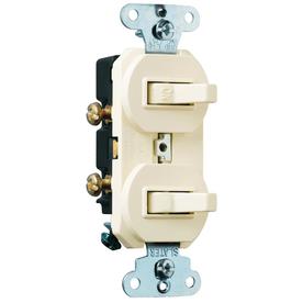
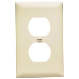
Notice that this combo switch would use a single gang receptacle plate rather than a switch plate. The mounting screw at the top and bottom and the plate screw are all size 6/32.
(Photos by http://www.lowes.com)
Rating Excellent A ☺ (Photos by http://www.lowes.com)
This method is commonly used when 2 switches need to be in a single gang location.
Level Intermediate
Description Power is fed to the combo switch by pulling a 2 wire feed from the nearest source of power. Then 2 switch legs are pulled from the switch to a ceiling fan. A 3 wire has 2 switch legs in it; a red for the light and a black for the fan with the white being used as the neutral. If you have no 3 wire available you could pull two 2 wires which would leave you with an extra white neutral. One black for the light the other black for the fan and one of the whites for the neutral.
A line diagram and wiring schematic of a combination switch with a light and a fan.
Many new ceiling fans come with a remote that can control the light and the fan. This eliminates the need for the second single pole switch. Since the unused switch is connected to an unused wire that is up at the ceiling, it it possible that one could go up into the attic and connect a new wire to this unused wire (and the neutral) and add some new can lights that could then be controlled by the unused switch.
S1 Method #5-1 Multiple Single Poles For One Fan
Rating Excellent A+ ☺A rare method used to control a single exhaust fan from 2 or more different bathrooms. The exhaust fan is located in a central location, like an attic, and connected to duct work that comes from all (lets say) 3 bathrooms. Each bathroom has a single pole switch that can turn the fan on or off but the fan can only be turned off at the place where it is turned on.
Level Advanced
Description Power is fed to a disconnecting switch located near the fan. A 2 wire switch leg is pulled from the fan to the 1st closest bathroom switch and another 2 wire from the 1st switch to the 2nd and another 2 wire from the 2nd to the 3rd. The white in the 2 wire is identified with black tape and used as a hot, not a neutral and not the switched hot that connects to the fan.
At the fan box; the hot feed is connected to one terminal on the disconnecting switch. The white (with black tape) is connected to the other terminal on the disconnecting switch and feeds power to one terminal on each bathroom single pole. The black switch leg is connected to the other terminal on each bathroom single pole and then directly to the fan. The white from the fan is connected to the white neutral in the feed.
A line diagram and wiring schematic of a fan controlled by 3 single pole switches.
Keep in mind that these single poles are not 3ways or 4ways meaning that the 1st S1 cannot turn off the fan if the 3rd S1 is in the on position. The fan is off when the disconnect switch (switch 1-2) is on and all 3 S1s are off (switches 3-8, 4-7 and 5-6) The fan is on when the disconnect switch and any one or more of the S1s are also on as shown here;
The fan is off when the disconnect switch is off and cannot be turned on by any bathroom S1 allowing you to work on the fan safely as shown here;
I hope you found this information useful.
No comments:
Post a Comment