S1 Method #2-1 Light Fed Single Pole
✓ There is no neutral at the switch that might be needed for specialty switches.
Level Intermediate
Description
Power (a hot and a neutral) is fed to the light (not the switch) with 1 switch leg run from the light to the switch. A 2 wire (14/2 or 12/2) feed is pulled from the nearest source of power like a receptacle directly to the light box and another 2 wire switch leg is pulled from the light to the switch.
Rating Average C ☹
Although this method is common and used often in older houses, it gets a low rating because;
✓ It is difficult to reach the important junctions behind a light, high on the ceiling.
✓ It creates an electrical hazard. The wires at the light will be hot even when the switch is off.
Level Intermediate
Description
Power (a hot and a neutral) is fed to the light (not the switch) with 1 switch leg run from the light to the switch. A 2 wire (14/2 or 12/2) feed is pulled from the nearest source of power like a receptacle directly to the light box and another 2 wire switch leg is pulled from the light to the switch.
Refer to the drawings below for these connections at the light box; Connection #1 The black hot feed L1 is connected to the white wire in the 14/2 switch leg. Connection #4 The black switch leg (#3 to #4) is connected to the black going to the light (#4 to #5). Connection #7 The white from the light (#6 to #7) is connected to the white neutral in the feed (#7 to N).
| Numbers in the Line Diagram above correspond to the connections in the wiring schematic and photo below. Electricians use line diagrams to help them figure out complex wiring connections. |
 |
| Photo of S1 Wiring Method #2 A light fed single pole switch. http://singlepole.blogspot.com by Jim Morelli |
This "Light Fed S1" method uses the white wire as a hot. (From #1 to #2) There is no neutral at the switch. There is a white wire at the switch but it is not a neutral. The neutral from the feed goes directly to the light. (From N to #7 to #6).
But, why would you use a white as a hot?
Answer, because 14/2 NM-B cable (and 12/2) comes with 3 wires; a black,a white and a ground. This switch wiring method requires 2 blacks from the light to the switch instead of 1 black and 1 white. When this happens the white wire is used as a hot. You might be able to special order 14/2 with 2 blacks and a ground but it is likely to cost more, take 2 weeks and require a minimum order of 250 feet. Nah, just put black tape on the white wire as shown, you don't have to cover the entire wire.
There are 2 code rules about using a white wire as a hot:
- Mark it with a black marker or black tape near the ends of the white wire
- It must be used as a hot feed (from #1 to #2) not the switch leg (from #3 to #4).
✓ Unfortunately this method of connecting the hot and neutral inside the light box, instead of inside the switch box, makes it very difficult to access the those connections if any troubleshooting is required. If something is miswired in the light box you might have to go back up a 12 foot ladder and take down a 50 pound chandelier to access the connections in the ceiling light box unaware that one of the wires will still be hot. Beginners will think the wiring in the light box is dead when the light is switched off, but the hot wire that runs from a receptacle directly to the light will still be energized unless the circuit breaker is turned off.
Question; A single pole switch does not need a neutral, so why would you want a neutral in the switch box?
Question; A single pole switch does not need a neutral, so why would you want a neutral in the switch box?
Answer; Because changes or additions might require a neutral. Since there is no neutral in the switch box you cannot;
- Install a digital timer - Install a motion sensing switch. - Install a remote controlled switch - Pull a wire to a 2nd light from the switch box. (You will have to come off the first light.) - Pull a wire from the switch box to add a nearby receptacle. (You will have to find another power source.)
S1 Method #3 Switch Fed, Switched Receptacle

Level Intermediate
Description

Level Intermediate
Description
S1 Method #3.3 Half Switched and Fed Receptacle

If you want to add a 2nd, new receptacle below this switch and you run a new 14/2 from this switch box to feed the new receptacle below you have a problem; there is no neutral at this switch box. You would have to feed your new receptacle from the first one shown here, even if it is 10 feet away.
S1 Method #3 Switch Fed, Switched Receptacle
Rating Excellent A+ ☺
Level Intermediate
Description
Both the top and bottom outlets on the receptacle are switched on and off by a wall switch.
Power is feed to the switch with a 14/2 and a 14/2 switch leg is run to the receptacle.
S1 Method #3.1 Switch Fed, Half Switched Receptacle
The best way to wire a half switched receptacle because it has a neutral at the switch box where it may be needed for other applications. The method is often used in bedrooms to switch on lamps.
Rating Excellent A+ ☺
Level Intermediate
Description
Only the top half of the receptacle is switched on and off by a wall switch. The bottom outlet is hot all the time. Power is fed to the switch with a 14/2. A 14/3 is run from the switch to the receptacle using the red wire as a switch leg, the black as an unswitched hot and the white as a neutral. The factory tab that connects the top hot terminal screw with the bottom hot terminal screw is removed. Only the hot tab is removed not the neutral tab. The tab is removed by grabbing it with pliers and bending it back and forth until it breaks loose.
S1 Method #3.2 Switched and Fed Receptacle
Rating Average C ☹
There is no neutral at the switch and that can be a disadvantage if you need that neutral for something else at the switch box.Level Intermediate
Description
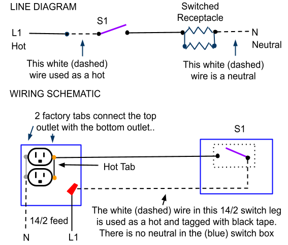
Both the top and bottom outlets on the receptacle are switched on and off by a wall switch.
Power is feed to the receptacle with a switch leg run to the switch.
A 2 wire is pulled from a nearby power source like a hot receptacle or the electrical panel, to feed the switched receptacle. Another 2 wire switch leg is pulled from the switched receptacle to the switch. The white wire in the 2 wire switch leg is tagged with black tape and used as a hot.
S1 Method #3.3 Half Switched and Fed Receptacle
Rating Average C ☹
There is no neutral at the switch and that can be a disadvantage if you need that neutral for something else at the switch box.
Level Intermediate
Description
There is no neutral at the switch and that can be a disadvantage if you need that neutral for something else at the switch box.
Level Intermediate
Description
Only the top half of the receptacle is switched on and off by a wall switch. The bottom outlet is hot all the time. Power is feed to the receptacle with a 14/2 and a 14/2 switch leg is run to the switch.
The white wire in the 14/2 switch leg is tagged with black tape and used as a hot. The factory tab that connects the top hot terminal screw with the bottom hot terminal screw is removed. Only the hot tab is removed not the neutral tab.
The white wire in the 14/2 switch leg is tagged with black tape and used as a hot. The factory tab that connects the top hot terminal screw with the bottom hot terminal screw is removed. Only the hot tab is removed not the neutral tab.
If you want to add a 2nd, new receptacle below this switch and you run a new 14/2 from this switch box to feed the new receptacle below you have a problem; there is no neutral at this switch box. You would have to feed your new receptacle from the first one shown here, even if it is 10 feet away.
excellent instructions ! If I can follow your schmatics . I can solve my problem . I am trying to fix someone elses error in connecting a light to a switch that is connected to a double wall plug and then to a old type fuse box .. We will see what happens . Thanks
ReplyDeleteOK Great Hope you got it.
DeleteFantastic and useful we blog thanks for publishing this.it's useful and informative.keep up the great.
ReplyDeleteWiFi Smart Wall Switch Home Automation